QFP Probing Adapters

QFP Probing (Carrier Adapters) and QFP Clip
Ironwood’s QFP Carrier Adapters are two-piece systems that allow for the probing and socketing of QFP devices. The bottom assembly is a surface mount foot (emulating the QFP package) that solders onto the target system’s QFP lands. The foot presents an array of gold plated pins to the upper probing assembly, which “carries” the IC device and presents gold plated test point pins for each signal. The upper assembly is available with a ZIF socket (-Z parts) or less expensive surface mount lands (-S parts) as in the drawing to the right.

These two piece QFP probing adapter assemblies are sold in the on-line catalog as a single package, however, the surface mount foot is also offered separately as the SF- part number described in the “Compatible Part” column.
The QFP Clip allows probing of individual pins on a QFP IC soldered directly to SMT pads. A fastener is attached to the top of the IC and the QFP clips makes contact to each of the QFP pins with spring pins. The 2.54mm pitch header pins are then connected to each pin on the QFP to allow logic analysis or scope probing for all pins. The header pins and spring pins are gold plated for highest reliability connection.
CA-QFP with ZIF Sockets
These QFP probing adapter upper assemblies incorporate a high quality ZIF socket. ZIF sockets may be open top or clamshell, depending on the package. Refer to the drawing for the selected part.
CA-QFP with SMT Lands
The IC device is soldered directly to surface mount lands on the upper assembly. These are the least expensive, yet most electrically stable, of our QFP probing adapter upper assemblies. In some cases, the option of square or rectangular pads is offered.
CL-QFP
Reliable probing adapter for SMT mounted QFP.
SMT Emulator Base Details
Ironwood’s QFP package emulators utilize either the typical gull wing or one of our less expensive, smaller, but more reliable “leadless” systems. The drawing below details some of the differences and advantages of the different technologies.
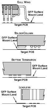
SURFACE MOUNT BASE DETAILS
The drawings at left detail the solder joint formed between the target land patterns and each respective Surface Mount Foot (SMF) type.
We make four types of QFP SMF bases:
- Gull Wing (-G)
- SolderLink (-F)
- Bottom Termination (-K)
- Leadless (-L)
The various SMF types designed for the same QFP package will vary dimensionally due to the geometry required to facilitate soldering. Typically the perimeter of the leadless and bottom termination type SMF is slightly smaller than the tip to tip dimension of the package being emulated. A shaped solder (“SolderLink”) SMF designed for the same package would have a slightly larger perimeter dimensions than the package being emulated.
The gull wing, leadless and bottom termination type SMF are all conducive to hand soldering. The SolderLink, gull wing and leadless type SMF can be reflowed to the target PCB with conventional production reflow methods.