Spring Pin Sockets (ESS)


Sockets for High Temperature & High Endurance Applications
The Spring Pin Socket line allows very high endurance and wide temperature range testing of 0.3mm to 1.27mm pitch BGA, LGA , QFN, QFP and SOIC devices on the same footprint as other Ironwood socket technologies. This allows different PCB’s with same footprint to accomplish many different test applications.
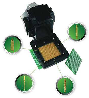
Spring pin sockets provide high bandwidth in a small, cost effective design. Spring pin socket is a simple, mechanical socket based on Pogo (spring) pin technology. Spring pin socket is a solder-less socket that can be mounted on to a PCB using supplied hardware. The PCB should have mounting and alignment holes at proper locations (page 2 of the individual socket drawing shows recommended PCB layout information). The typical Spring pin socket footprint is only 5mm larger than the maximum IC size which means series resistors, capacitors, tuning inductors and others can be placed minimal distance from IC in GHz applications. The socket is mounted to the PCB with a backing plate and for all IC body sizes, spring pin sockets require a rigid metal backing plate to prevent deflection of the target circuit board due to a high normal force required to compress the spring pins. If the backside of the target PCB contains capacitors and resistors, a custom insulation plate with cavities cut for those components can be designed. This insulation plate sandwiches between the backing plate and target PCB. The socket is constructed of aluminum to dissipate up to several watts without extra heat sinking and can handle up to 100 watts with custom heat sink. The user simply places the IC into the socket, closes the lid, and rotates the heat sink screw to connect the IC. It is compatible with the alternate elastomer socket footprint and other socket technologies as well. If there are pre-existing holes in the PCB, a Spring pin socket can be custom designed to accommodate those holes (please call Ironwood Tech Support @1-800-404-0204).

Typical spring pin socket with clam shell lid is shown in the figure. If there is no room to put mounting holes for socket on a customer’s board, the socket can be used with SMT options or with Thru hole options.
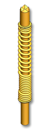
The spring pin functions as the interface between the IC package and the circuit board. The spring pin used in the socket is a low-resistance (<0.05 ohms) connector. 0.3mm center – double ended spring pin is shown in the adjacent picture. Double ended spring probes are primarily comprised of two plungers and spring. The spring (gold plated stainless steel or music wire) is sandwiched between two plungers (gold plated hardened Beryllium Copper). The spring has open coils and closed coils. Both plungers interface in the closed coil area enabling signals pass straight through as oppose to loop through coils. The spring probes has current rating in the range of 1A to 8A based on geometry and material selection. The operating temperature range is -55C to 150C for Stainless steel spring version and -55C to 125C for Music wire spring version. The solder balls from the IC package come in contact with the crown end of spring pin. The bottom end of spring pin contacts the circuit board pad, completing an electrical path for the signal. These spring probes can be customized very easily for specific test height, force, plating finish, materials, etc.
Custom sockets to accommodate rectangular body shapes, odd sizes, and devices with specific contactor requirement can be developed in short lead-time. You can fill the form with required information or call us at 1-800-404-0204.